Posted 2019/9/23
Contents List
The features of NF Current amplifier, which is useful for detecting a very-small-current signal, are introduced below.
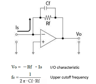
A general current amplifier consists of an op-amp and a feedback resistor.
A basic circuit is shown in Figure 1. The gain of this circuit is determined by feedback
resistor Rf. And the upper cutoff frequency is determined by feedback capacitor Cf and Rf.
Since it is determined by Cf and Rf, the upper cutoff frequency of current amplifier cannot be
increased even using an operational amplifier with a large gain bandwidth.
Figure 1: Current amplifier using feedback method
In order to expand the bandwidth, it is necessary to reduce Cf capacitance. However, in general,
it is difficult to make Cf smaller than 0.1 pF due to the parasitic capacitance of components
and circuits.
If the feedback resistance Rf is 10 GΩ and the feedback capacitance due to parasitic
capacitance is 0.1 pF, the upper cutoff frequency is 160 Hz at maximum. At 0.1pF feedback
capacitance, the relationship between the feedback resistance (Rf) and the upper cutoff
frequency is shown in Table 1.
Table 1: Limits of upper cutoff frequency due to feedback capacitance
| Feedback resistance Rf (Ω) | Feedback capacitance Cf (F) | Upper cutoff frequency (Hz) |
|---|---|---|
| 10M | 0.1p | 160k |
| 100M | 0.1p | 16k |
| 1G | 0.1p | 1.6k |
| 10G | 0.1p | 160 |
| 100G | 0.1p | 16 |
| 1T | 0.1p | 1.6 |
On our SA-600/CA-550/CA-650 series, by devising and adjusting circuit configurations and
components mounting method, it is realized to reduce equivalent feedback capacitance due to
parasitic capacitance to less than 0.1 pF and achieve increasing upper cutoff frequency.
The relationship of our SA-600/CA-550/CA-650 series between upper cutoff frequency, feedback
resistor (gain) and equivalent feedback capacitance are listed in Table 2.
Table 2: Upper cut-off frequency, feedback resistance, and equivalent feedback capacitance of NF SA-600/CA-550/CA-650 series
| Model name | Upper cutoff frequency fc (Hz) | Feedback resistance Rf (Ω) | Equivalent feedback capacitance Cf (F) |
|---|---|---|---|
| SA-604F2/CA-554F2/CA-654F2 | 500k | 10M | 32f |
| SA-605F2/CA-555F2/CA-655F2 | 250k | 100M | 6.4f |
| SA-606F2/CA-556F2/CA-656F2 | 100k | 1G | 1.6f |
| SA-607F2/CA-557F2/CA-657F2 | 20k | 10G | 0.8f |
| SA-608F2 | 2k | 100G | 0.8f |
| SA-609F2 | 300 | 1T | 0.53f |
Equivalent feedback capacitance:
Feedback capacitance
calculated from upper cutoff frequency and feedback resistance.
The comparison of upper cutoff frequency between our SA-600/CA-550/CA-650 series and other manufactures is shown in Table 3. As clear from Table 3, these our products achieves wide bandwidth characteristics exceeding those of other manufactures.
Table 3: Comparison of upper cutoff frequencies
| Gain (V/A) | NF's SA-600/CA-550/CA-650 Series (Hz) | Company A Constant gain model (Hz) | Company C Variable gain model (Hz) |
|---|---|---|---|
| 10M | 500k | 400k | 23k |
| 100M | 250k | 40k | 8.8k |
| 1G | 100k | 4k | 3.5k |
| 10G | 20k | 200 | 1.4k |
| 100G | 2k | 200 | 1.4k |
| 1T | 300 | 30 | - |
*Investigation on December 8, 2022
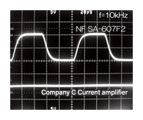
Figure 2 and figure 3 show pulse-response waveforms when a square-wave with an input current of ± 5 nA. In the figures, NF's SA-607F2 is compared to company C's current amplifier. Both gains are 10 GV/A. In the case of the 1-kHz pulse shown in Figure 2, the rise time of the SA-607F2 is 20-times faster than that of company C's current amplifier. Moreover, company C's current amplifier cannot amplify the 10-kHz signal; However, the signal output through SA-607F2 is clearly shown.
Figure 2: Pulse-response waveforms at f=1 kHz
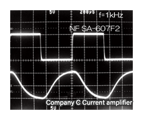
Figure 3: Pulse-response waveforms at f=10 kHz
*Investigation on June 16, 2017
Rise time
| Company name | Product name | Rise time |
|---|---|---|
| NF | SA-607F2 | 13µs |
| Company C | Current amplifier | 260µs |
Related keywords : Ultra low noise amplifier, LNA
