Posted 2019/9/23
There are two main methods to reduce voltage noise after signal amplification below.
In order to reduce noise, it is effective to set an appropriate measurement band, that is, to remove noise components in unnecessary frequency bands. In particular, even if the noise amplitude level is the same, the noise at higher frequency has larger energy, so it is important to remove unnecessary high-frequency noise component.
The output waveforms with and without a low-pass filter (LPF) (1-pole, fc = 1 kHz) to the output of the current amplifier are shown in Figure 11. By using LPF, it is seen that the noise is reduces and the output waveform become very sharp. In this way, by setting only the signal of the band to be measured by a technique such as filtering, S/N ratio can be improved and a smaller current signal can be detected. In addition, as an actual measurement example, a 1-pAp-p real-time signal was successfully detected using SA-607F2.
Figure 11: Comparison of output waveforms due to difference in measurement bandwidth
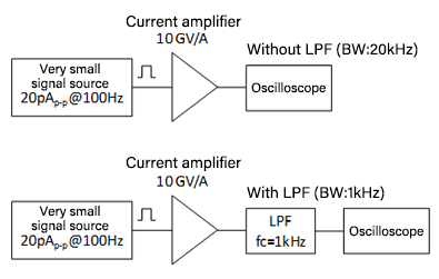
(a) Block diagram of measurement
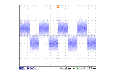
(b) Output waveform without LPF (BW: 20 kHz)
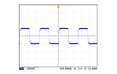
(c) Output waveform with LPF (BW: 1 kHz)
Guidelines of the measurement band settings for signal waveform measurement are shown in Table
6.
Note that Table 6 only shows guidelines, and the appropriate measurement band may varies
depending on the customer’s measurement content. For that reason, various filters are provided.
Table 6: Guidelines for setting the measurement band suitable for the signal waveform to be measured (when using LPF)
| Measured signal waveform | Cutoff frequency of LPF |
|---|---|
| Sine wave | 3–5 times higher than the signal frequency |
| Square wave | About 10 times higher than the signal frequency |
| Triangle wave | 7–10 times higher than the signal frequency |
Table 7: Various filter products
| Type | Overview | Product |
|---|---|---|
| Cutoff frequency that can be set freely |
|
|
| Multichannel analog-signal-preprocessing system that makes it possible to configure filters, differential amplifiers, isolation amplifiers, etc. according to the required number of channels |
|
|
| Board-mounted type filter module |
|
|
| Power-supply storage case with built-in filter module | A storage case that can built-in various filter modules is available. |
Even with the proper measurement system and measurement conditions, a small signal from the sensor may be buried in noise and not observed in real time measurement. Even in this case, it may be possible to detect small signals by averaging. The conditions under which small signals can be detected by averaging are as follows.
Block diagrams of the measurement system and the output waveforms of the current amplifier with
and without averaging are shown in Figure 12. It can be seen that the averaging enables
detection of very small current signals buried in noise.
In averaging, it is important to set the measuring range of the measurement instrument
appropriately. Then let’s discuss how to utilize the averaging function of oscilloscope. When
the signal exceeds the voltage measurement range of oscilloscope, the part of the waveform that
exceeds the measurement range is clamped, so signals cannot be detected accurately. Also, if the
voltage measurement range is too wide and the detected signal level is under the measurement
resolution, the signal cannot be detected regardless of reduction of random noise by averaging.
Therefore, it is important that dynamic range setting of the measurement instrument for the S/N
ratio improvement by the averaging.
In this way, it is important to set the appropriate measurement instrument and measurement range
in consideration of the signal level to be measured and the noise level superimposed on the
signal.
Figure 12: Comparison of output waveforms with and without by averaging

(a) Block diagram of measurement
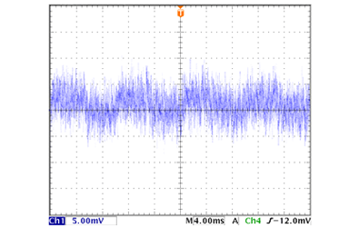
(b) Output waveform without averaging
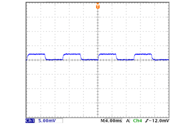
(c) Output waveform with 512-times averaging
Related keywords : Ultra low noise amplifier, LNA