|

|
 |
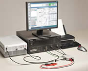
Configuration:
Main unit (measurement and analysis), monitor (display),
keyboard, trackball (pointing device),
* Can be
connected a printer to the main unit. (Recommended
printer: HP Officejet 100, HP Officejet H470)
|
 |
Highly reliable
measurements for a wide range of
measurement objects |
|
|
|
 |
|
 |
Capable of measuring
from ultra-low frequency ranges
Measurement frequency: 0.1 mHz to 15 MHz |
|
|
|
Supports measurement of power
devices and high-voltage circuits
Maximum input voltage: 250 Vrms; Dynamic range: 140 dB |
|
|
|
Extensive range of measurement sweep
parameters and high density
sweeping of the frequency axis
Sweep parameters: Frequency, AC amplitude, DC bias, time
|
|
|
|
Isolation between all inputs and
outputs
Isolation voltage: 250 Vrms |
|
|
|
Functions available to provide
improved measurement data reliability
Open/short correction, integration and equalization, etc.
|
|
|
|
Amplitude compression
(pseudo-constant current output measurement) |
|
|
|
A wide array of optional peripheral
devices are available, such as a power amplifier for
amplifying the driving signal and fixtures for the
measurement of various items. |
|
Upgraded measurement
and analysis efficiency!
Smooth utilization of data and
smooth system linkages |
|
|
|

 |
Results from a simulator: Who
knows what they mean?
Conventional LCR meters and impedance analyzers
can’t measure what you need! |
|
| To correctly evaluate the characteristics of
electronic components and circuits, it’s fundamental
to make measurements in an actual operating environment.
|
|
| |
| Impedance Measurement of Electronic
Components |
Inductors and capacitor are used in large
quantities in electronic equipment. To design
high-performance equipment, it’s extremely important
to accurately know the characteristics of electronic
components used in equipment. LCR meters or impedance
analyzers are generally used for measuring electronics
components; however, measurable voltage and current are as
small as a few volts and about several milliamperes. Some
components are used under a voltage of 100 V or higher and
current of 10 A or higher. The values measured by LCR meters
and impedance analyzers may differ from those of actual
operating conditions.
ZGA5920 provides measurements under actual operating
conditions, with its
• High-voltage input, • Wide dynamic range, • Isolation between inputs
and outputs,
• High-voltage,
high-current power driver amplifier and • Measurement adapter with a
current detector circuit. In measuring and evaluating
piezoelectric elements that are used as actuators, it really
excels.
|
|
| Measurement of Loop
Gain of the Switching Regulator |
To evaluate the stability of the circuit, loop
gain is measured. ZGA5920:
• Injects the signal into the
loop, and measures the open loop gain under closed loop
operating conditions.
• Automatically calculates
the phase margin and the gain margin that are used in
quantitatively evaluating stability. |
|
|
|
|
|
|