Posted 2019/7/19
So how do we choose a preamplifier?
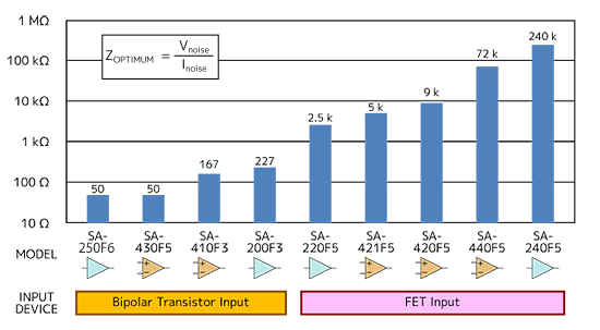
As a performance index of a preamplifier, an impedance value (ZOPTIMUM) obtained by the following formula is used.
ZOPTIMUM[Ω] = (Equivalent input noise voltage density
[V/√Hz] ÷
(Equivalent input noise current density [A/√Hz])
ZOPTIMUM is a measure of the signal-source impedance at which the preamplifier can demonstrate low noise. As for a preamplifier, signal-source impedance below ZOPTIMUM is a desirable signal source.
ZOPTIMUM is calculated as follows: for SA-250F6, it is given by 0.25 nV/√Hz÷5.0 pA/√Hz=50 Ω; for SA-220F5, it is given by 0.5 nV/√Hz÷200 fA/√Hz=2.5 kΩ.
According to the calculated value, a suitable preamplifier for a sensor is determined. Equivalent input noise voltage density (including the signal-source impedance of the preamplifier) is given by the following formula.

In this equation, Vn is equivalent input noise voltage density [V/√Hz] of the amplifier itself, In is equivalent input noise current density [A/√Hz] of the amplifier itself, R is signal-source impedance. (output impedance of sensor, etc) [Ω], KB is Boltzmann’s constant [J/K], and T is absolute temperature [K].
By using this equation to simulate the output impedance of the sensor when one of three resistors with different resistances (0 Ω, 50 Ω, and 1 kΩ) is connected to the input, it is possible to determine whether SA-250F6 or SA-220F5 is classified as low noise.
Values of ZOPTIMUM and equivalent input noise voltage density when the resistors are connected are listed in Table 1. Also, thermal-noise values (signal source) at room temperature of the connected resistors are also listed.
With the 0 Ω resistor is connected (i.e., with the input shorted), SA-250F6 provides good low-noise performance. Connecting the 50 Ω resistor will make a difference between SA-250F6 and SA-220F5, but very small. However, when 1 kΩ resistor is connected, SA-220F5 attains lower noise than SA-250F6.
SA-250F6 uses a bipolar transistor as the input device. In the bipolar transistor, a base current is flowing when the transistor operates. Due to the base current, equivalent input noise current density also increases. Since the current is converted into a voltage when it flows through the resistor, the larger resistance, the greater effect of equivalent input noise current density.
On the contrary, the input of SA-2205F is connected to a junction field-effect transistor (junction FET or JFET). Only a very small amount of current flows in the gate of the FET; therefore, equivalent input noise current density stays at a small value.
As a result, when considering actual connections and operations of a sensor, the FET input often shows better noise characteristics than the bipolar-transistor input.
Table
| Pattern | ZOPTIMUM | 0 Ω | 50 Ω | 1 kΩ |
|---|---|---|---|---|
| SA-250F6 | 50 Ω | 0.25 nV/√Hz | 0.98 nV/√Hz | 6.45 nV/√Hz |
| SA-220F5 | 2.5 kΩ | 0.50 nV/√Hz | 1.04 nV/√Hz | 4.11 nV/√Hz |
| Reference: Thermal noise of signal source | N/A | 0 nV/√Hz | 0.91 nV/√Hz | 4.07 nV/√Hz |
ZOPTIMUM of the SA series is shown in Figure.
In some cases, ZOPTIMUM cannot be read from the data sheet of the preamplifier.
In such cases, as a guideline, it is recommended that a preamplifier with input impedance more than 10 times the signal-source impedance is selected. For example, if source impedance is 100 Ω, then, input impedance of 1 kΩ or more is recommended.
In the case a sensor with unknown signal-source impedance is to be used, and a preamplifier that can be used for general purposes without limiting its application is also to be used, it is recommended to select first a preamplifier that adopts an FET input.
Figure
Related keywords : Ultra low noise amplifier, LNA
