Posted 2019/7/19
The shorter the connection between the signal source and the preamplifier, the better. Ideally, the input end of the preamplifier should be directly connected to the signal source.
In reality, however, the signal source and the preamplifier are often separated. In this case, they are connected by electric wire. Since the electric wire works as an antenna, which can easily contain noise. For this reason, the correct choice of wiring is important.
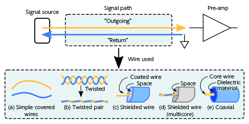
The simple case in which two wires are simply routed and connected is shown in Figure 1(a). It is the easiest, but not for noise prevention and it is not suitable for transmitting small signals.
The development of the simple connection is the “twisted pair” as shown in Figure 1(b). The “outgoing” and “return” signals are combined, making this configuration less affected by external noise. Note that in another configuration, instead of the two wires being twisted, they are simply stuck together in parallel; however, the twisted pair is better in terms of noise immunity.
As shown in Figure 1(c), the outgoing signal is shielded by the return-signal “covering” wire. By covering the entire circumference of the outgoing signal, it is less affected by external noise. However, nothing but empty space exists between the outer circumference and the core wire, and that situation brings the disadvantage that the capacity between the cables is undefined. For that reason, this configuration is suitable for DC and low-frequency signals, but its high-frequency characteristics are inadequate.
Figure 1(d) shows the means of combining the configurations shown in Figures 1(b) and 1(c). External noise is absorbed by the outer-shield wire, and the inside consists of a twisted pair to obtain good transmission characteristics. If the signal is roughly up to 10 kHz, this wire configuration exhibits excellent characteristics.
In the configuration shown in Figure 1(e), the hollow part of the configuration shown in Figure 1(c) is filled with a dielectric (insulator), and this configuration is called “coaxial.” Capacitance per unit length and characteristic impedance are determined as standards, so it is easy to obtain good transmission characteristics with this configuration.
In general, the signal line in measurement applications is often the same as that shown in Figure 1(e). The reasons for this include the facts that cable characteristics are standardized, coaxial connectors such as BNC and SMA are commonly used, and transmission characteristics up to high frequencies are excellent.
Figure 1

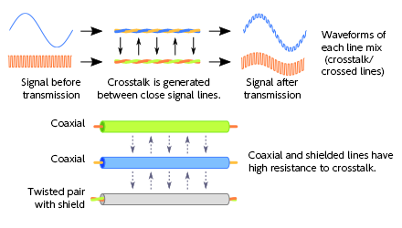
It is also common to bundle multiple signal lines or to wire them closely. The problem with such a configuration is that the signal “jumps” between close signal lines and causes leakage called “crosstalk” (Figure 2).
The signal wire covered with a shield is the wiring configuration with high resistance to crosstalk. Since the shield also absorbs external noise, it can be said that shielding is indispensable for the transmission of a very small signal.
Figure 2

Related keywords : Ultra low noise amplifier, LNA