The DP series has a variety of output modes and a wide output range.
|
|
|
100 V range
|
200 V range
|
Resolution
|
|
AC
|
Voltage
|
AC: 0 V to 175 V
ACHF: 0 V to 160 V
ACDC: 0 V to
160 V
|
AC: 0 V to 350 V
ACHF: 0 V to 320 V
ACDC: 0 V to
320 V
|
0.1 V
|
|
|
AC: 40 Hz to 1500 Hz, ACHF: 1 Hz to 5000 Hz,
ACDC: 1 Hz to 1500 Hz
|
0.01 Hz
*
|
|
DC
|
Voltage
|
-227 V to +227 V
|
-454 V to +454 V
|
0.1 V
|
|
|
*
Varies depending on the frequency.
|
|
|
AC/DC modes: AC, ACHF, ACDC, DC
|
|
|
Output current fluctuation: ±0.1 V (50 V ~ 160 V)/ ±0.2 V (100 V ~ 320 V)
(DC, 10 Hz ~ 100 Hz, when output current is changed from 0% to 100% of the maximum current)
|
|
|
Distortion of waveform: 0.3% or lower (40 Hz ~ 550 Hz)
|
|
|
Efficiency: 80% or higher
|
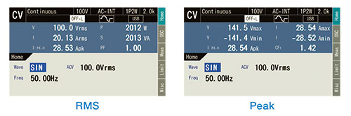
In addition to voltage, current, and power, the DP020A supports load power factor, load crest factor, and harmonic current up to 50th order of the fundamental wave.
* This measurement does not conform to the IEC standards.
|
 Measurement Items Measurement Items
|
|
|
|
|
Voltage: RMS value, average
DC
value, peak value
|
|
|
Current: RMS value, average
DC
value, peak value, peak hold value
|
|
|
Power: active power and
apparent
power
|
|
|
Harmonic analysis
*
: up to 50th order
|
|
|
Load power factor
|
|
|
Crest factor
|
|
|
Sync frequency
|
|
*
Not conforming to IEC standards.
|
Equipped with a current limiter that can limit current with peak value (positive or negative) and RMS value. This is effective in protecting against overcurrent caused by abnormal load operation. Even a load with a large inrush current can be continuously driven by limiting the current with the limiter, eliminating the need to install a power supply with a large power capacity to match the inrush current.
|
|
|
Setting range
|
|
|
Peak value for Positive/Negative current and RMS value
|
|
|
Limiter operation
|
|
|
Select whether to recover automatically (continuous) or turn the output off when the limited state continues over the specified time (1s ~ 10s, resolution 1s)
|
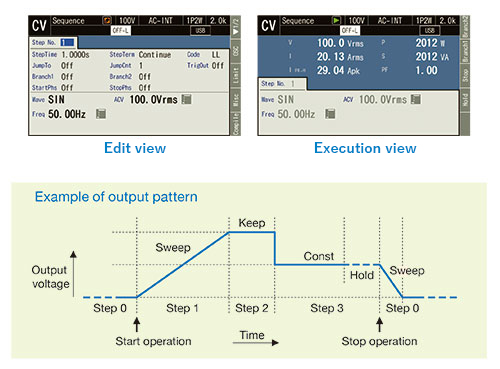
By using the sequence function, an output setting can be changed step-by-step according to the program (sequence) created beforehand. Setup can be done on the device panel or from the control software provided separately. Long and complex output patterns can be easily programmed with the software.
|
|
|
Number of steps: Max. 255 (for each sequence)
|
|
|
Parameters:
|
|
|
Step time, Output range, AC/DC mode, DC voltage, AC voltage, Frequency, Waveform, Start phase, Stop phase, Phase angle, Step termination, Jump count, etc.
|
|
|
Sequence control :
Start, Stop, Hold, Resume, Branch 1, Branch 2
|
|
|
Number of memories: 5 (non-volatile)
|
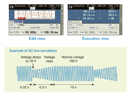
This simulation function allows editing of output voltage patterns which simulate power line abnormalities such as blackout, voltage rise, voltage drop, abrupt phase change, and abrupt frequency change. It supports various kinds of simulations for prototype evaluation and product inspection. Setup can be done on the device panel or from the control software provided separately.
Note: This simulation function does not support the standard tests defined by organizations such as IEC.
|
|
|
Number of steps: 6
(Initial, Normal 1, Trans 1, Abnormal, Trans 2, Normal 2)
|
|
|
Parameters :
|
|
|
Step time, Output range, AC voltage, Frequency, Start phase, Stop phase, Trigger output, etc.
|
|
|
Waveform: Sine wave
|
|
|
Number of memories: 5
(non-volatile)
|
|
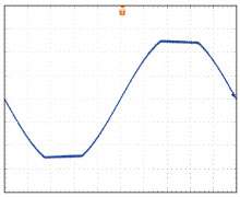
Clipped sine wave / Arbitrary waveform
|
|
|
|
Test waveforms other than sine wave can be set.
|
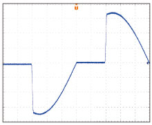
| Clipped sine wave
|
The peak clipped sine wave can be generated,
based on the crest factor (CF) setting or
the percent setting to the peak value.
- CF variable range: 1.10 ~ 1.41
- Clip ratio variable range:
40.0% ~ 100.0%
- Number of memories: 3 (non-volatile)
|
 |
| Arbitrary waveform
|
This uses the waveform data saved in the internal memory,
which is transferred and recalled using the external
interface (control software) or USB memory.
- Amplitude resolution: 16-bit
- Waveform length: 16k words
- Number of memories: 16 (non-volatile)
|
 |
|
Full of convenient features
|
|
|
|
 |
Remote sensing
This switches the voltage used for measurement. When the remote sensing is on, the sensing input terminal voltage is used. When it is off, the output terminal voltage is used. |
|
|
Control software
It is possible to control basic output parameters, acquire measured value data, perform sequence and simulation, and create and edit arbitrary waveforms.
* Downloadable from our website. |
|
AGC (Automatic Gain Control)
When the AGC is on, the detection point voltage is always measured, and the output voltage is continuously corrected so that its effective value is equal to the output voltage setting value. |
|
|
Setting range limit function
The range of the output voltage as well as frequency to the internal signal source can be limited. This can prevent mis-setting when you do not want to set values outside the range.
|
|
Autocal (Automatic calibration)
When the Autocal is on, the detection point voltage is always measured, and the output voltage is continuously corrected so that its effective value is equal to the output voltage setting value.
|
|
|
Output setting at power-on
Output can be set to turn on automatically when power is turned on.
|
|
USB memory
USB memory allows writing/reading of basic setting data, Sequence data, Simulation data and Arbitrary waveform data. This is useful for making the same settings for many power supplies or for reading data created by the control software. |
|
|
High impedance to turn the output off
This function turns off the output in a high impedance state. Output can be turned off without discharging capacitor or battery.
|
|
External signal input
SYNC synchronizes the frequency of the internal signal source with the one of the external signal sources.
VCA controls the output voltage setting with a DC signal.
EXT amplifies an external signal.
ADD adds an external signal source to the internal signal source.
|
|
|
Output relay control
Select either ON/OFF using output relay or output OFF with 0V not using the relay.
|
|
The output on/off phase setting
The setting range is 0° ~ 359°. This is useful for measuring inrush current. |
|
 |
|
|
|
|
|